
Seismic Snubbers
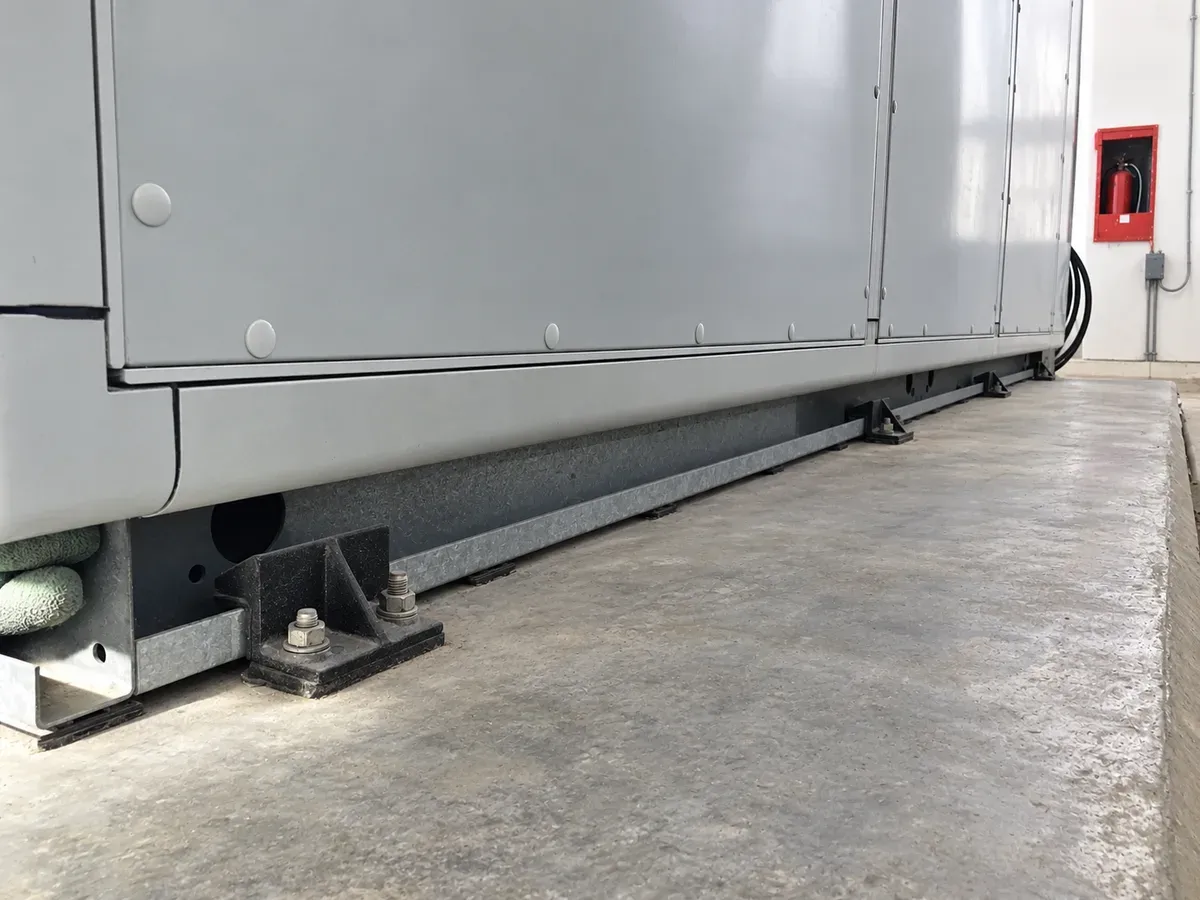
Restraints that stand beside open springs and rubber mounts and stay out of contact in normal running. In an earthquake or high wind they catch the equipment within 6 mm (1/4″), on rubber-lined faces that take the edge off the shock load.
The range
Chosen by direction, then by load
A snubber is selected for the directions it has to hold, then sized to the force. We supply snubbers directly, selected and placed with the seismic calculation for the equipment.
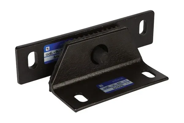 AS-A
All-Directional Snubber
Two interlocking parts, one fixed to the structure and one to the equipment, rubber-lined on every contact face.
All directions · in pairs on opposite sides · up to 10,000 kgf as standard
Ask us for a selection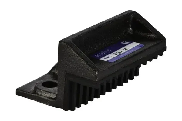 AS-Z
Uplift & Lateral Snubber
Holds lateral movement and uplift; placed on all four sides of the equipment to assure all-directional restraint.
All directions · 3.5 mm rubber cushion · up to 2,500 kgf as standard
Ask us for a selection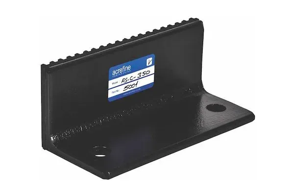 AS-C
Lateral Snubber (Bumper)
Holds horizontal movement only, for equipment with no risk of overturning or uplift.
Lateral only · at least four, facing in from every side · up to 6,000 kgf as standard
Ask us for a selection
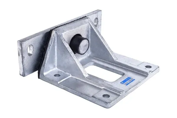
Tailor-Made Snubbers
Loads above the standard range, a hot-dip galvanised finish, or a snubber shaped to the equipment itself, such as a chiller delivered on flat steel legs. We design it to the equipment and the seismic demand.
Above 10,000 kgf · galvanised on request · shaped to the equipment base
Ask us for a selectionDatasheets, installation guides and certificates Downloads
Selection
Which way does it need holding?
Tall or narrow equipment can overturn and lift off its isolators; low, wide equipment mostly slides. The answer decides the snubber, and the calculation decides how many and where.
| Criterion | AS-A | AS-Z | AS-C |
|---|---|---|---|
| Holds | Lateral movement and uplift | Lateral movement and uplift | Lateral movement only |
| Placement | In pairs, on at least two opposite sides | On all four sides | At least four, facing in from every side |
| Use when | Heavy equipment that can overturn: chillers, generator sets, large pumps on inertia bases | Air handling units, packaged units and fans on springs or rubber pads | Low, wide equipment with no risk of overturning: tanks, skids and inertia bases on a level floor |
| Rubber cushion | 7 mm ribbed pad (API-S) | 3.5 mm | 7 mm ribbed pad (API-S) |
| Standard capacity | Up to 10,000 kgf | Up to 2,500 kgf | Up to 6,000 kgf |
Above the standard range, or equipment with an unusual base? We design tailor-made snubbers for the project.
Featured solution
Marmaray, Istanbul
The rail tunnel beneath the Bosphorus, one of the largest infrastructure projects in Türkiye’s history. Before construction began, we carried out the complete seismic design of the tunnel’s electromechanical systems for Taisei Corporation.
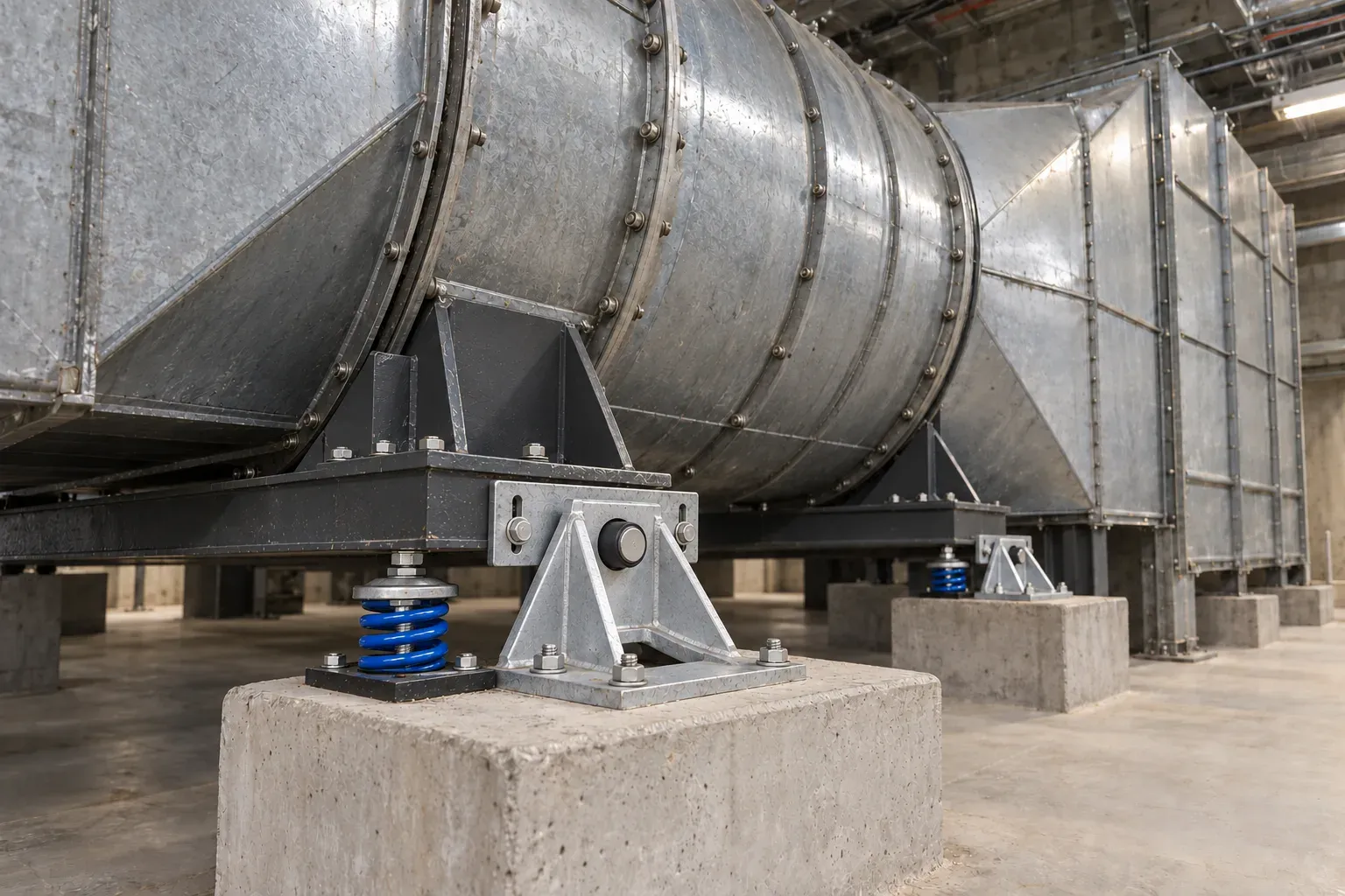
We then supplied the products to the MEP contractor, Anel, and stayed with them on site for shop drawings and supervision: tens of thousands of seismic cable restraints, nearly every product in our range, and tailor-made AS-AR snubbers rated to 10,000 kgf under ventilation fans up to 2.8 m in diameter. The largest project in our history.
Learn moreSeismic restraint
Isolator and restraint, side by side
Equipment on open springs or rubber pads is free to move; that is how it isolates. A snubber stands beside the isolator, clear of the equipment in normal running, and closes on it only when the building shakes: the equipment stays resiliently mounted yet seismically restrained, with the gap held within 6 mm (1/4″).
A snubber holds in the directions it faces. All-directional restraint comes from placement: AS-A in pairs on opposite sides, AS-Z on all four. Uplift is held by the snubber’s own geometry and its fixing to the structure, not by a washer under a nut on the equipment bracket.
Every contact face is lined with rubber, so the first contact is cushioned rather than steel on steel. We size the snubbers and the isolators together, so the spring deflection and the snubber gap work as one system.
Related products

Related engineering services

Describe the equipment and what it stands on.
We will select the snubbers, place them and size them to the seismic demand.