
Data Centre Safety Engineering
Fire, smoke, battery and seismic risk engineering for facilities where downtime is measured in minutes
- BS 6266
- BS EN 50600
- NFPA 855 (opens in a new tab)
- NFPA 68
- BS EN 14994
- NFPA 13 (opens in a new tab)
- BS EN 15004
- NFPA 2001
- Your local code
Four risks
Each with its own path to the same outage
- 01Fire & SmokeData halls are an unusual fire problem.Details
- 02Battery, UPS & Energy StorageWhen a lithium cell goes into thermal runaway, the hazard is not primarily the flame.Details
- 03Water & Liquid EscapeWater is the loss nobody models and everybody pays for.Details
- 04Seismic Restraint & IsolationA rack that stays standing but loses a connection has still caused an outage.Details
In a data centre, the cost of an incident is rarely the cost of the damage. It is the cost of the outage — and that changes what safety engineering has to achieve. A fire strategy that protects life and limits structural damage may still permit an event that takes a hall offline for weeks. Battery rooms, cooling plant, water services and seismic restraint each carry their own failure path to the same outcome, and each is usually designed by a different party. Acrefine’s data centre safety engineering looks at those paths together: how a fire or a thermal event actually develops, what the suppression and smoke strategy does to the equipment as well as to the fire, and what it takes for the facility to be operational again afterwards.
Since September 2024, UK data centres have been formally designated Critical National Infrastructure — the first new CNI designation in almost a decade. The designation does not itself impose new fire or structural requirements, but it has raised what operators, insurers and planning authorities expect to see evidenced about resilience and continuity.
01Fire & Smoke
Data halls are an unusual fire problem. The combustible load is low relative to the value at risk, but it is not negligible — cable insulation and containment, equipment plastics and, increasingly, in-rack lithium battery back-up units all contribute. What makes detection genuinely difficult is airflow: at data hall air change rates, smoke from an incipient fire is diluted as it is carried away from the source far faster than it would be in still air, so a detector selected on general principles may not see a developing fire until well past the stage at which intervention would have been cheap. BS 6266 addresses this by requiring correspondingly higher detector sensitivity. Suppression carries the mirror-image problem: the agent and its discharge conditions have to be judged against what they do to running equipment, not only against what they do to the fire.
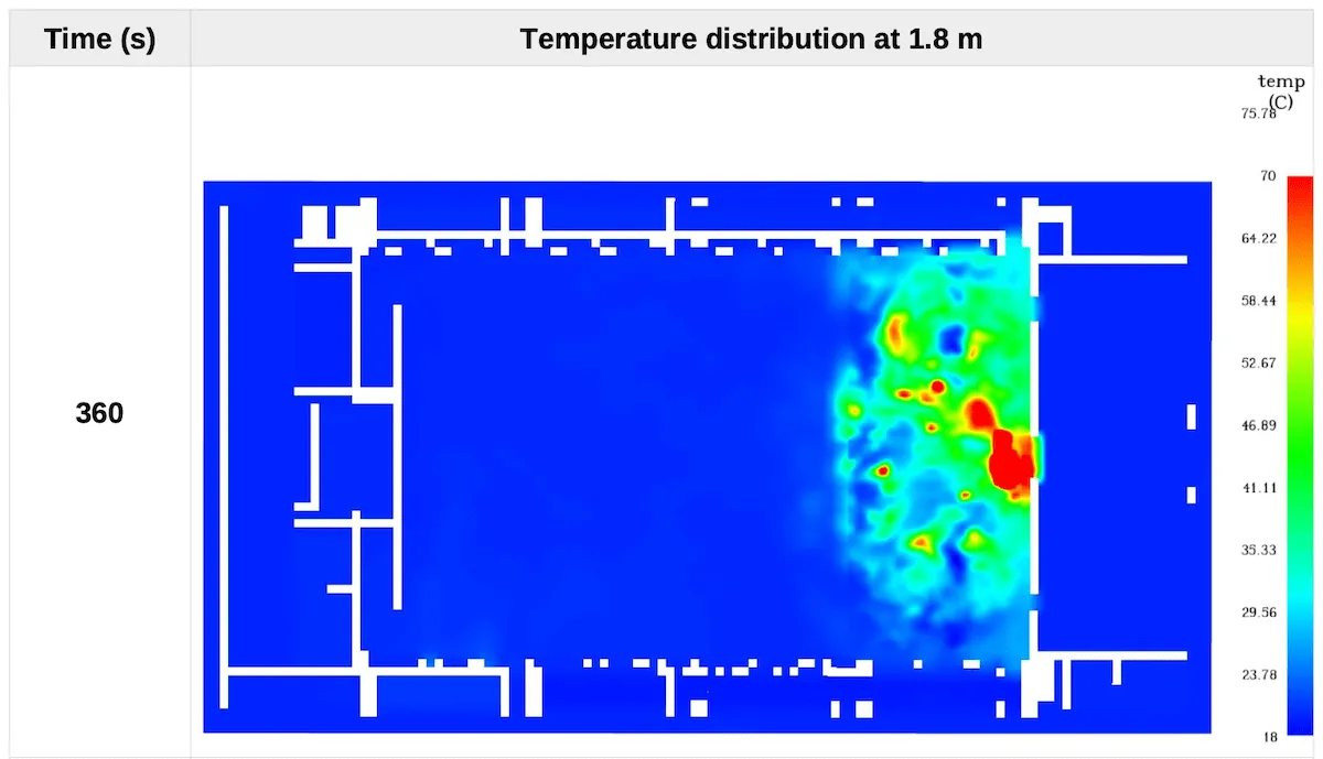
We review the fire and smoke strategy for the facility as designed, model the behaviour where geometry or air movement makes the outcome uncertain, and identify where detection, suppression and containment choices do not match the risk the room actually presents.
What we offer
- Fire and smoke risk review of the facility as designed, against BS 6266 and BS EN 50600
- Very early warning / aspirating detection strategy review for high-airflow halls, including detector sensitivity justification
- Clean agent and inert gas suppression review — agent selection, room integrity and discharge overpressure venting
- Smoke movement and extraction modelling for data halls, plant areas and generator rooms
- Compartmentation and containment review across halls, electrical rooms and risers
- Thermal ride-through assessment on loss of cooling — how long the hall holds before thermal shutdown, and what that means for response time
- Fire strategy input for planning and building control submissions
02Battery, UPS & Energy Storage
This is where the most consequential change in the last two years has happened, and where we do our most technically demanding data centre work.
When a lithium cell goes into thermal runaway, the hazard is not primarily the flame. It is the flammable and toxic gas the cell vents before ignition — gas that accumulates in the room, may ignite as a deflagration rather than as a fire, and propagates cell to cell along a path that depends on the rack layout, the ventilation and the enclosure geometry. Suppression alone does not address this. The room has to be understood as a gas dispersion and explosion-control problem before it is treated as a fire problem, which is why the analysis belongs upstream of the equipment selection rather than after it.
The 2026 edition of NFPA 855 has moved in this direction. Hazard Mitigation Analysis — previously required only above certain stored-energy limits — is now the default for nearly all energy storage installations, and the standard has added requirements covering active thermal runaway propagation prevention, off-gas detection as a precursor signal, and unit-level testing that includes intentional ignition of vent gases to assess the deflagration hazard. For data centres this is not a distant threshold: NFPA 855 engages at 20 kWh of stored energy for lithium-ion and 70 kWh for lead-acid and nickel-based systems, which most UPS installations of any scale exceed. What used to be satisfied by product listings increasingly requires facility-specific analysis.
What we offer
- Hazard Mitigation Analysis for battery, UPS and energy storage rooms
- CFD modelling of vent-gas dispersion and accumulation under thermal runaway scenarios
- Explosion control and deflagration venting assessment to NFPA 68/69 or BS EN 14994, coordinated with the ventilation design
- DSEAR-facing assessment of flammable gas accumulation in battery spaces
- Thermal runaway propagation assessment across rack and module arrangements
- Off-gas and early-detection strategy review
- Ventilation and mechanical extract verification for battery room gas management
- Review of UL 9540A and large-scale fire test evidence supplied by equipment vendors
Where a facility’s chemistry or capacity falls below the thresholds that trigger a formal Hazard Mitigation Analysis, the same modelling is still the fastest way to answer the question an operator or insurer will ask: what does this room do in the hour after a single cell fails.
03Water & Liquid Escape
Water is the loss nobody models and everybody pays for. Across FM Global’s long-run data centre loss data, liquid-related damage accounts for roughly a quarter of total loss cost — split between sprinkler leakage and escaping liquid from cooling systems — making it the second-largest driver of loss cost after fire. Almost all of it arrives from services the facility installed itself: chilled water, humidification, condensate, sprinkler pipework, roof and drainage systems routed above or beside critical space. That makes it largely a routing and containment problem, designed out on a drawing rather than managed in operation — and it is becoming more acute as liquid cooling moves into the rack.
What we offer
- Water and liquid escape risk mapping across halls, plant rooms and risers
- Wet services routing review over and adjacent to critical space, including liquid-cooled rack deployments
- Containment, bunding, leak detection and drainage strategy review
- Sprinkler and pre-action system review where water-based suppression is required or retained
04Seismic Restraint & Isolation
Seismic and Vibration Restraint for MEP and Racks
This is Acrefine’s founding discipline, applied to a facility type where the tolerance for movement is unusually low. A rack that stays standing but loses a connection has still caused an outage, and cooling and power plant that survives a seismic event in a damaged state has still interrupted the service it exists to protect.
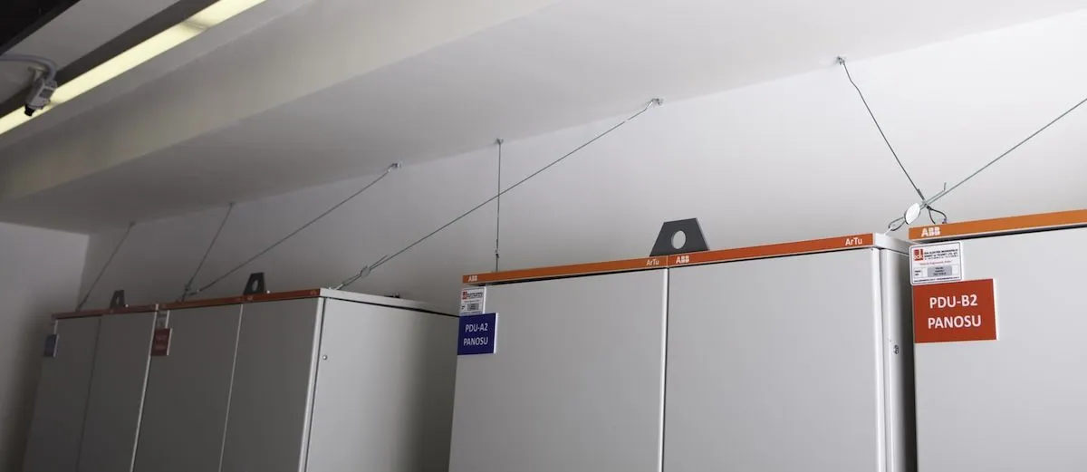
We design restraint for building services and IT equipment so that movement stays inside limits the systems and their connections can absorb, and so that the loads the restraint generates are carried predictably into the structure.
What we offer
- Seismic restraint design for MEP plant, pipework, ductwork, cable trays and busbar
- Rack, cabinet and containment restraint design and anchorage calculations
- Vibration isolation design for generators, chillers, pumps and CRAC/CRAH units
- Overturning and anchorage calculations for freestanding and mounted equipment
- Sprinkler and standpipe pipework bracing to NFPA 13’s seismic provisions where applicable
- Layout and installation drawings for site use
- Post-event operability assessment — what the facility can run on after a seismic event, not just whether it stood up
Seismic Isolation for Mission-Critical Facilities
Restraint keeps equipment attached to the building. Isolation changes what the building hands to the equipment in the first place — and in a data centre that distinction is the whole argument. Conventional seismic design is written to protect life and prevent collapse; it accepts that a compliant building may be shaken hard enough internally to take a facility offline. Isolation lowers the accelerations the racks, the cooling plant and the power train actually experience, which moves the objective from the building survived to the service never stopped.
That protection can be introduced at three levels, and choosing between them is usually the first useful conversation on a project. Base isolation at the structure’s foundation protects everything above it and suits new-build facilities where seismic performance is set as a design objective from the outset. An isolated floor or platform protects a defined hall or equipment room and is often the only route available in an existing building, where isolating the structure itself is not practical. Equipment- and rack-level isolation targets individual assets and can be retrofitted with minimal disruption, at the cost of leaving the rest of the facility on the building’s own response. Each level buys a different amount of protection for a different cost and disruption profile, and the right answer depends on the facility’s continuity requirement rather than on the seismicity alone.
Where most isolation projects go wrong is the services. An isolation system works by allowing the isolated structure to displace — often by several hundred millimetres relative to the ground. Every pipe, cable, busbar, drainage run, fuel line and containment route that crosses that isolation plane has to accommodate the same displacement without failure, and it has to do so while remaining serviceable afterwards. A building can be isolated correctly and still lose its chilled water or its power feed because a service crossing the plane was detailed as though nothing moved. This is the intersection where our two disciplines meet: structural seismic isolation on one side, and nearly three decades of building services seismic design on the other.
What we offer
- Seismic isolation concept advisory for data centres — base isolation, isolated floors and equipment-level isolation compared against the facility’s continuity requirement
- Feasibility and concept-level assessment for isolating an existing facility or hall
- Isolation plane services review — displacement demand on pipework, cabling, busbar, drainage and fuel routes crossing the plane
- Flexible connection and seismic joint specification for services crossing the isolation interface
- Floor response and equipment acceleration assessment — what the racks and plant actually see, isolated versus not
- Post-event operability review of the isolated facility as a whole
Business Interruption Engineering Note
Insurers and boards ask a question most fire and structural reports do not answer: not “is this compliant” but “what does the worst credible event cost us in downtime, and what would change that number.” The Business Interruption Engineering Note is a short, quantified engineering document written to be read by underwriters, risk managers and operations — translating the modelling into loss-scenario and recovery-time terms, in the form insurers survey against.
What we offer
- Loss scenario development for fire, battery, water, cooling-loss and seismic events
- Estimated downtime and recovery path per scenario, with the engineering assumptions stated
- Identification of the interventions that most reduce interruption exposure, ranked by effect
- Gap review against FM Global Data Sheet 5-32 (data centres) and 5-33 (energy storage)
- Engineering input to insurer surveys and risk-improvement schedules
Regulatory and Framework Context
Outside that case, the frameworks that shape data centre safety work are BS EN 50600 (with ISO/IEC 22237 as its international equivalent) for facility infrastructure — fire events originating within data centre spaces are addressed in Part 2-5 — BS 6266 for fire protection of electronic equipment installations, and the operator’s own resilience or availability classification. Where a facility is designed to an Uptime Institute Tier, we work to the resilience intent that classification implies; Tier certification itself is Uptime’s own proprietary scheme, awarded only by them, and we make no claim to deliver or substitute for it.
How We Work
Data centre work is carried out by an experienced multidisciplinary team spanning fire engineering, structural seismic engineering and building services. Concept and assessment work on seismic isolation is carried out by our structural seismic team, whose data centre experience spans seismic isolation consultancy for a national telecommunications operator’s data centre, non-structural seismic design for a major bank’s data centre, and peer review for a further banking data centre.
Standards and Technical Basis
Facility infrastructure work is framed by BS EN 50600 and its international equivalent ISO/IEC 22237, with TIA-942 used where a project’s international context calls for it. Fire protection of electronic equipment installations follows BS 6266; gaseous and clean agent suppression is designed to BS EN 15004 or NFPA 2001, with NFPA 75 (Fire Protection of Information Technology Equipment) applied on internationally-coded projects. Battery and energy storage work follows the IET Code of Practice for Electrical Energy Storage Systems in the UK and NFPA 855 where the project’s code basis calls for it, including the Hazard Mitigation Analysis it requires; vendor test evidence is assessed against UL 9540A, and explosion control and deflagration venting to NFPA 68/69 or BS EN 14994, with DSEAR as the UK legal driver for flammable gas accumulation. CFD and performance-based fire analysis follows the BS 7974 framework, with modelling substantiated against the FDS validation basis published in NIST Special Publication 1018. Seismic restraint and vibration isolation of non-structural components are designed to ASCE 7 Chapter 13, IBC or Eurocode 8 as the project’s code jurisdiction requires, with SMACNA restraint guidance where applicable. Seismic isolation work is framed by BS EN 15129 (anti-seismic devices) and ASCE 7 Chapter 17 for isolated structures, with isolator specification and testing referenced to the ISO 22762 series for elastomeric seismic-protection isolators. Insurer-facing work is reviewed against FM Global Data Sheets 5-32 and 5-33. The applicable standards set is confirmed project-by-project against the facility’s regulatory and contractual context.
Questions
Before you ask for a quotation
Is a data centre a Higher-Risk Building?
A purely commercial data centre is not a Higher-Risk Building under the UK Building Safety Act. That regime applies to buildings of at least 18 metres or 7 storeys that contain at least two residential units — and, during design and construction, to care homes and hospitals meeting the height threshold irrespective of residential units. A data centre’s own use class contributes nothing to that determination.
The distinction matters in one increasingly common case, and the mechanism runs the opposite way to how it is usually described. An edge or in-building data centre placed inside a building that is already a higher-risk building — a residential or mixed-use development meeting the height and residential-unit thresholds — does not make that building higher-risk; the building already was. What changes is that the data centre works themselves become higher-risk building work, requiring Building Safety Regulator building control approval before construction can start. Where that applies, we produce the same evidence-pack documentation described on our fire safety engineering page.
Do you sign off the fire strategy or the structural design?
Acrefine’s role is the technical analysis, modelling and documentation that feed the sign-off process. Where a project requires formal sign-off — the fire strategy, or structural and isolation design — that sign-off rests with the project’s appointed engineers: a registered fire engineer and a chartered structural engineer holding the competency the project requires. Our work is built to feed their process, not to substitute for it. Where a project needs full structural seismic assessment rather than the data-centre-specific view, see our base isolation page.

Describe the facility and the risk you need answered.
We will tell you which of these it takes.